
OPGW Hardware & Fitting Tension Assembly
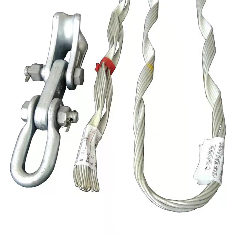
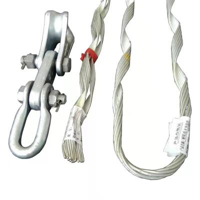
OPGW optical cable tension clamp is composed of inner stranded wire, outer stranded wire, embedded ring, U-shaped ring, extension ring, bolt, nut, closed pin, etc.
Function: This product is used for linking with poles and towers in the erection of opgw optical cable lines. The aluminum-clad steel pre-stranded wire protects the opgw optical cable and improves the seismic resistance.
Product Details
Features:
1. The application force has no concentrated point, the stress is uniform, and it has a good protective effect on the optical cable.
2. Under the premise of not exceeding the lateral compression strength of the optical cable, it has a greater grip on the optical cable and can withstand greater tension.
3. The grip strength of the optical cable is not lower than the cable-level limit resistance, such as the tensile strength (uts) of 95, which is fully suitable for the needs of optical cable erection.
Strength: According to customer needs, the configured strength is 70KN, 80KN, 100KN, 120KN, etc. Weight: 4.2KG
Dimensions: 1650MM
Material: Aluminum Clad Steel
Category: For OPGW
Product composition diagram

Product technical specification sheet:
Sn | Model No. | Cable range |
1 | ONY 0780 | 7.2-7.8 |
2 | ONY 0880 | 7.9-8.8 |
3 | ONY 1010 | 8.9-10.1 |
4 | ONY 1140 | 10.2-11.4 |
5 | ONY 1280 | 11.5-12.8 |
6 | ONY 1410 | 12.9-14.1 |
7 | ONY 1550 | 14.2-15.5 |
8 | ONY 1730 | 15.6-17.3 |
9 | ONY 1920 | 17.4-19.2 |
10 | ONY 2110 | 19.3-21.1 |
Conditions of Use: Used for the connection of terminal towers, tensile towers, towers with large height differences, towers with a rotation angle (elevation angle)> 25, and connecting towers.
Installation steps:
1. Align the installation mark of the outer wire with the optical cable and mark the installation.
2. Align the first set of inner wire marks with the optical cable marks.
3. The third group does the same as the second group.
4. All the inner wires are installed.
5. Align the outer wire installation mark with the inner wire installation mark.
6. Wrap one leg first.
7. Wind the other leg again.
8. Wrap the end of the outer wire well.
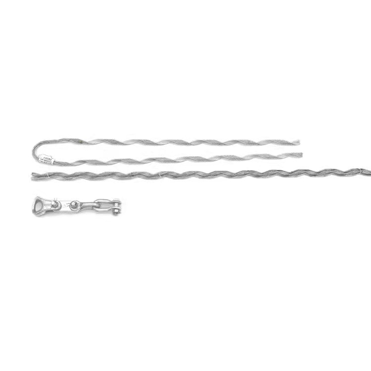
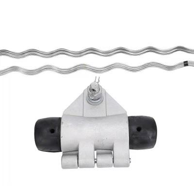
Product form
Related News
Advantages of Anchoring Bracket Clamp
2022-11-14
What are the wires included?
2022-10-25
Submitted successfully
We will contact you as soon as possible
Close